On this foam pusher wing, the battery and avionics sit between the nose module and the rear motor. The bay photos show the main power leads, servo runs, and where the FPV antenna exits the foam.
Elevon linkage geometry
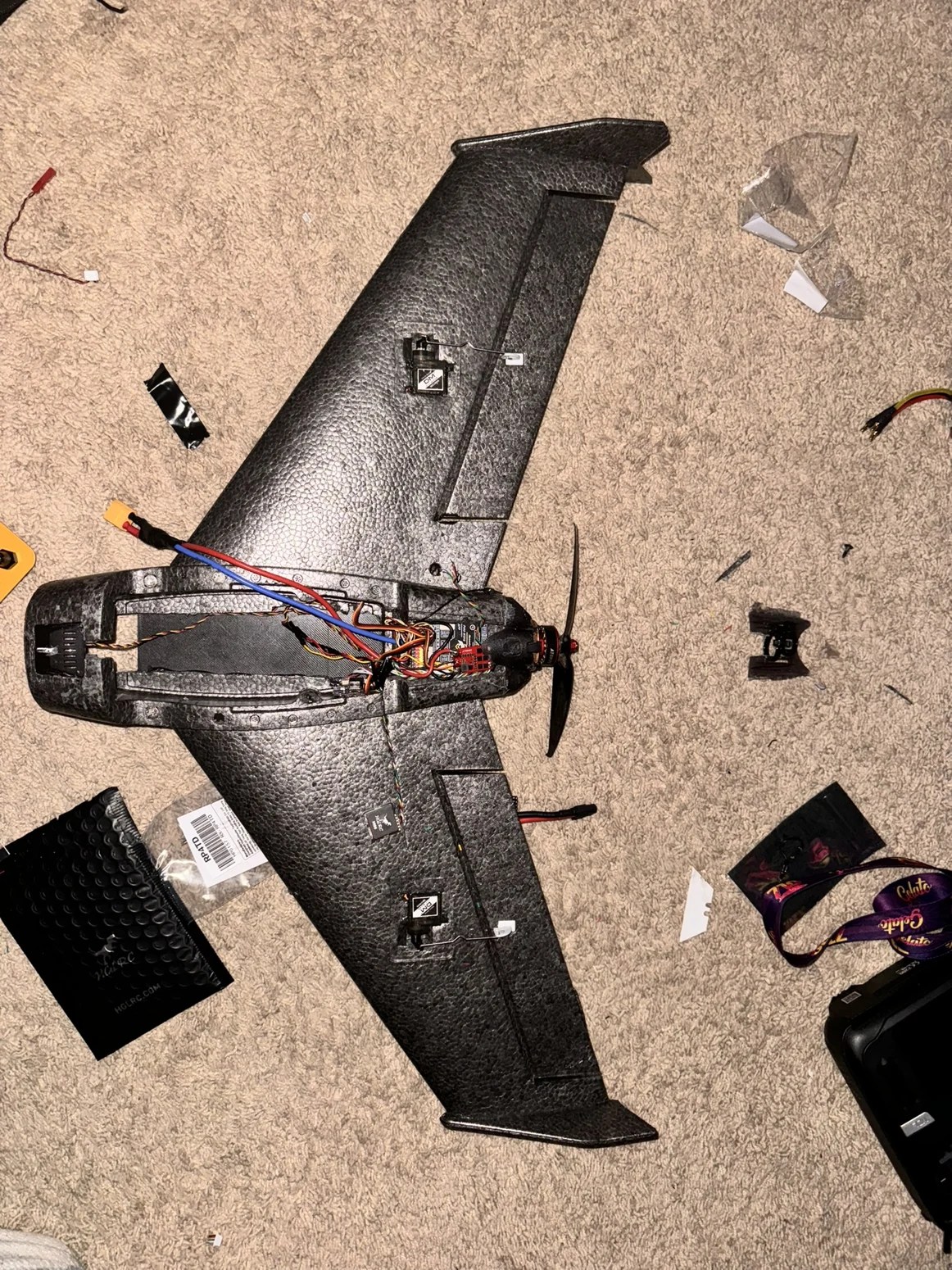
Each elevon has a short pushrod from a recessed servo. I check combined pitch and roll at the corners of stick travel. That’s where the mix can drive one surface farther than either input alone.
A longer servo arm gives more pushrod travel for the same servo rotation. A longer control horn gives less surface deflection for that travel. Both change where the rod sweeps past the foam.
Battery leads and antenna routing
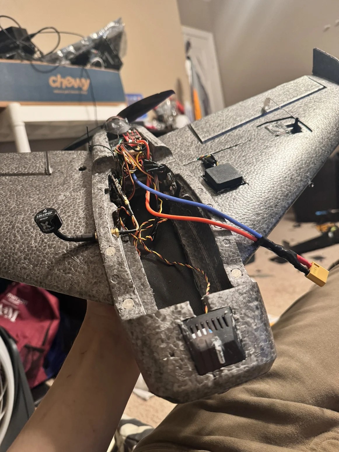
The red and blue power leads cross the battery pocket. The Foxeer Lollipop exits through the side. If I move the pack to set the CG, I need to check that the cover doesn’t pinch the leads against the foam.
I’d support the coax where it exits the body so handling the wing by the center section doesn’t transfer the load to the connector.
Wiring near the rear prop
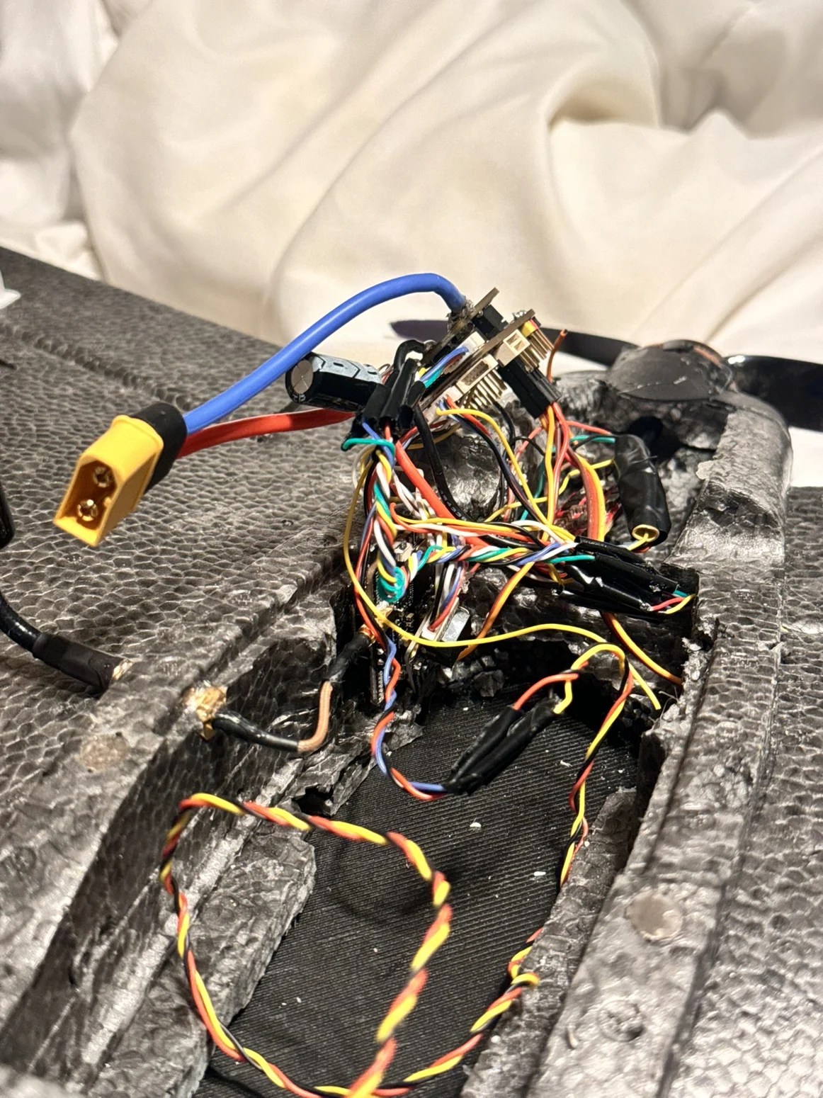
The power leads and signal harnesses come together just ahead of the motor. I need enough slack to reach the connectors with the bay open, and enough restraint to keep that slack clear of the prop.
For a separate installation with a shaped wood mounting plate, see Inside a Flying Wing Avionics Bay.

