BUILD LOG / FIXED-WING AIRCRAFT / AVIONICS INTEGRATION
Across my foam-aircraft projects, the integration work includes controller mounting, motor-power routing, navigation hardware, and fitting the electronics around the airframe. The photographs here open up several of those installations, including a twin-motor configuration.
These are installation notes across the photographic record, not a claimed sequence for one aircraft. Similar controllers and mounting details can appear in different airframes. The hardware is visible; a complete configuration and flight-test history is not.

Giving the controller a mechanical home
The SpeedyBee F405-WING label is visible on the board. An orange printed bracket spans the installation, with fasteners and spacers holding the assembly over the fuselage channel. The point of a bracket like this is to establish a repeatable mechanical reference while leaving access to the electrical connections.
That reference matters because an inertial sensor measures the motion of its own mounting. A board that rocks independently of the airframe can report motion that is not representative of the aircraft. A very rigid mount can also transmit vibration. The photographs establish the mounting arrangement, but deciding whether it isolates the right frequencies requires sensor data.
Two motors, one electrical installation
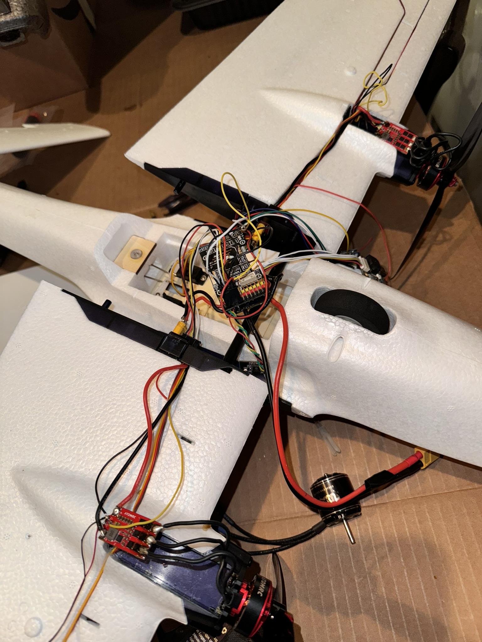
The open-airframe view shows a motor and an ESC at each side, a central electronics stack, and the wiring connecting the installation. The useful distinction is between the battery-current path and the control signals. The motor current does not flow through a servo signal lead: each ESC switches power to its motor, while its control input carries the command.
Two propulsion branches make routing and inspection more involved. Both branches need sound power connections, and their wiring has to clear the structure and moving parts. Extra wire makes bench access easier but adds mass and more opportunities for a lead to move. A photograph of a solder joint can expose an inspection target; it cannot establish its resistance or reliability under load.
Power regulation and navigation belong in the same discussion
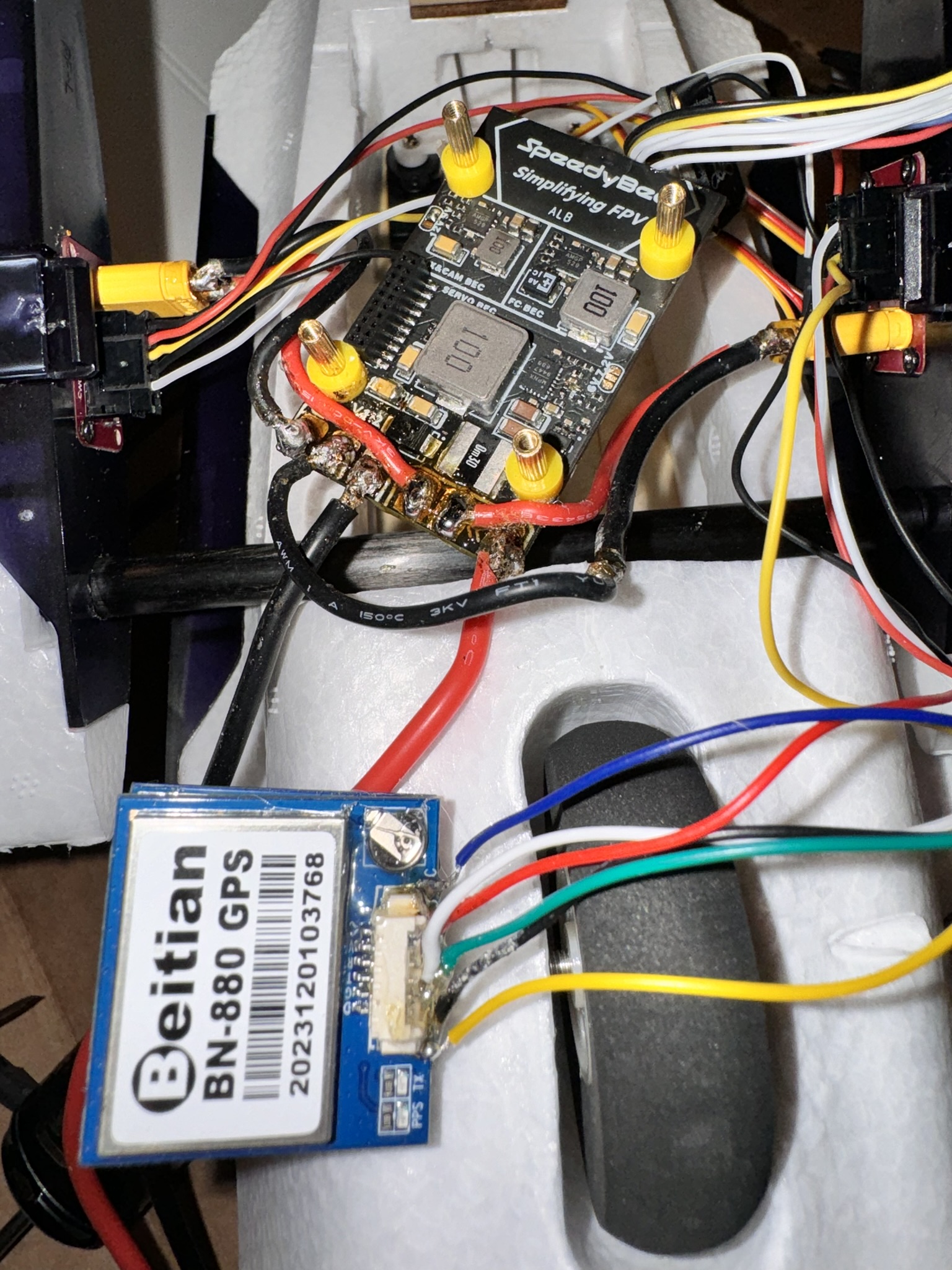
The power-board silkscreen distinguishes the servo supply from the flight-controller supply. That is a useful architectural separation: actuators create changing loads, and the controller needs a stable supply while those loads change. The actual rail voltages and current margin in this aircraft need measurement; the board’s labels are not a record of those measurements.
The BN-880 label identifies the GPS module in this configuration. Its presence does not establish a valid position solution, compass calibration, or successful autonomous navigation. Those are separate commissioning questions. In a compact installation, the routing around switching electronics and high-current conductors is worth inspecting alongside the software setup.
Service access is part of the design
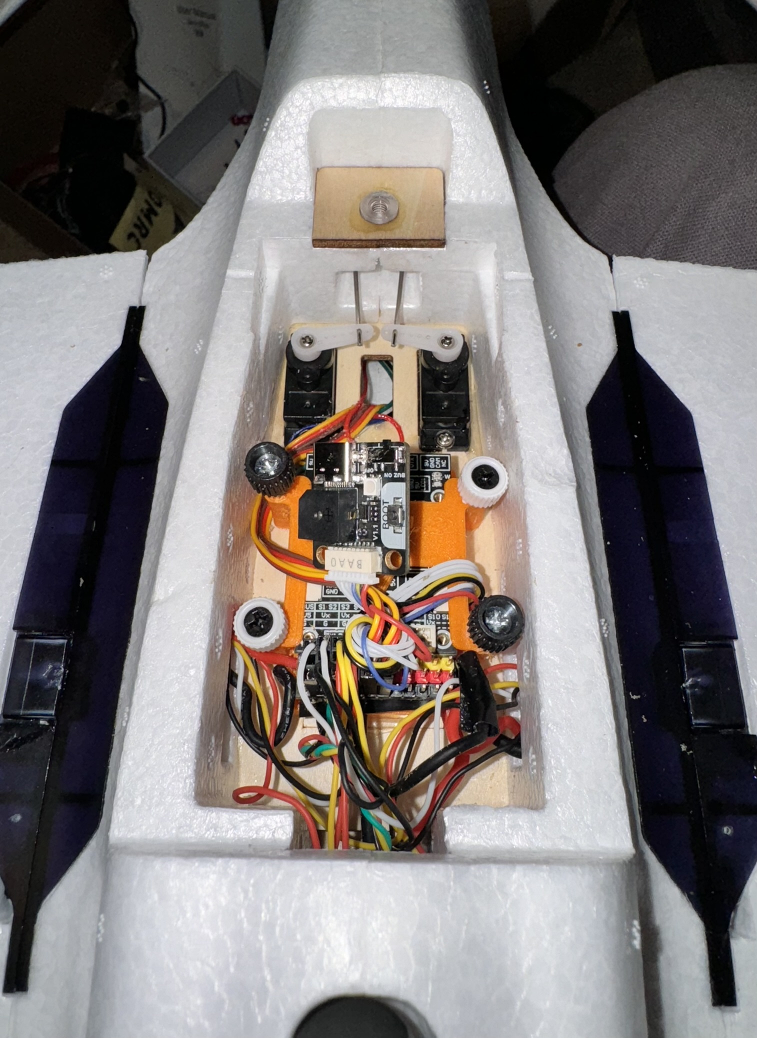
This view makes the packaging constraint clearer. The electronics share the bay with the control linkages, so a wire that fits while the aircraft is still may obstruct a moving part later. Access to the fasteners, connectors, and board edges matters when a component has to come back out.
I would preserve these views together rather than present them as a proven before-and-after sequence. They document comparable mechanical and electrical arrangements, but the photographs alone do not tell us which configuration flew last or which changes were retained.
What the build record establishes
The record shows SpeedyBee-based controller mounting, twin-motor power wiring, GPS hardware, servo connections, and printed mounting arrangements across foam-aircraft installations. It does not yet include a configuration export, exact firmware revision, measured center of gravity, current traces, or a flight log tied to these photographs.
Those missing records matter because they turn an assembly history into a testable aircraft history. The next useful additions are specific: a wiring diagram, the saved controller configuration, and flight data that can be matched to a photographed configuration.
Hardware reference: SpeedyBee F405 WING APP documentation. Use the manual that matches the installed hardware revision; manufacturer capabilities are not flight-test results for this build.

